When Every Decibel Counts: Engineering the Foundation of RF and 5G Performance
“Why is the signal loss higher than our simulation predicted?”
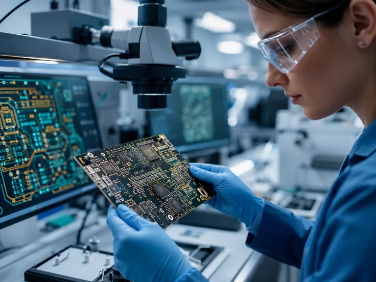
The RF engineer stared at the spectrum analyzer. The prototype passed basic connectivity tests, yet at 28 GHz the insertion loss exceeded tolerance. The root cause wasn’t firmware, shielding, or antenna design.
It was the High Frequency PCB material stack-up.
In RF and 5G systems, the printed circuit board is not just a carrier of components — it is part of the signal path itself. At microwave and millimeter-wave frequencies, dielectric constant (Dk), dissipation factor (Df), copper roughness, and impedance control directly determine system performance.
This article is a technical special report for engineers and OEM manufacturers. We will explore the top 10 real-world applications of High Frequency PCB technology in RF and 5G systems, supported by industry data, engineering principles, and insights drawn from manufacturing expertise at High Frequency PCB manufacturer.

Why High Frequency PCB Matters in Modern RF and 5G Systems
As wireless communication evolves toward higher bandwidth and lower latency, operating frequencies continue to rise:
-
Sub-6 GHz 5G systems
-
24–40 GHz mmWave 5G
-
77 GHz automotive radar
-
60 GHz WiGig
-
Satellite communication in Ku and Ka bands
At these frequencies:
-
Standard FR-4 materials introduce excessive dielectric loss
-
Copper surface roughness increases conductor loss
-
Impedance mismatches cause reflection and signal degradation
According to IEEE research, dielectric loss can account for over 40% of total signal attenuation in mmWave PCB transmission lines.
This is why advanced High Frequency PCB materials such as Rogers, PTFE-based laminates, and low-loss hydrocarbon ceramics are widely adopted.
Key Engineering Parameters of High Frequency PCB
Before diving into applications, it’s important to understand the core technical factors:
1. Dielectric Constant (Dk)
Lower Dk improves signal speed and reduces delay variation.
Typical values:
-
FR-4: ~4.2–4.8
-
High frequency laminates: 2.2–3.5
2. Dissipation Factor (Df)
Lower Df means less signal energy converted into heat.
-
FR-4: ~0.02
-
RF laminates: 0.001–0.005
3. Controlled Impedance
Tolerance typically maintained within ±5% for RF circuits.
4. Copper Surface Treatment
Smoother copper reduces conductor loss at high frequencies.
Manufacturers specializing in RF fabrication, such as jscircuit – About Us, invest in precision lamination, impedance testing equipment, and laser drilling systems to maintain tight tolerances.
|
|
|


Top 10 High Frequency PCB Applications in RF and 5G Systems
1. 5G Base Station Antenna Arrays
Massive MIMO systems require:
-
Precise phase matching
-
Low insertion loss
-
Stable dielectric performance
At 3.5 GHz and 28 GHz, even slight impedance variation disrupts beamforming accuracy.
High-performance High Frequency PCB substrates reduce phase error and maintain signal coherence across antenna arrays.
2. mmWave Small Cell Infrastructure
Small cell deployments in dense urban areas rely on compact RF modules operating above 24 GHz.
Engineering requirements:
-
Multilayer RF stack-ups
-
Thermal dissipation support
-
Tight impedance control
Signal attenuation at mmWave frequencies can increase 2–3 dB per inch if materials are not optimized.
3. Automotive 77 GHz Radar Systems
Advanced driver assistance systems (ADAS) use 77 GHz radar for collision detection and adaptive cruise control.
Challenges:
-
Extreme temperature range (-40°C to 125°C)
-
Vibration resistance
-
Ultra-low signal loss
Automotive radar modules demand high-reliability High Frequency PCB structures with stable dielectric properties across wide temperature cycles.
For OEM-level project discussions and RF stack-up consultation, engineering teams can connect via High Frequency PCB consultation.
4. Satellite Communication Terminals
Satellite ground stations and phased-array antennas operate in Ku and Ka bands (12–40 GHz).
Design priorities:
-
Low-loss microstrip routing
-
Stable phase delay
-
Moisture-resistant laminates
Research shows that humidity absorption can shift dielectric constant by up to 2% in standard materials — unacceptable for precision satellite links.
5. RF Power Amplifier Modules
High-power RF amplifiers require:
-
Thermal stability
-
Consistent impedance matching
-
Copper thickness optimization
Power amplifier efficiency can drop significantly when impedance drift exceeds tolerance.
6. 5G User Equipment (UE) RF Modules
Smartphones and IoT devices use compact RF front-end modules requiring:
-
Miniaturized multilayer boards
-
Integrated antenna structures
-
Signal isolation between high-speed digital and RF traces
Advanced High Frequency PCB fabrication ensures minimal cross-talk and stable signal integrity.
Manufacturing capability details are outlined in High Frequency PCB solutions, including multilayer RF board production and material compatibility.

7. Microwave Backhaul Systems
Telecom operators use microwave backhaul links operating between 6 GHz and 42 GHz.
Performance demands:
-
Low insertion loss
-
Stable long-distance transmission
-
High mechanical durability
Signal degradation directly affects data throughput.
8. Aerospace Communication Systems
Aircraft and defense systems require:
-
High reliability
-
Strict compliance standards
-
Resistance to altitude-related environmental stress
Rigid high-frequency boards are essential for radar and avionics control systems.
9. Industrial RF Monitoring Equipment
Factories deploy RF monitoring for:
-
Wireless sensors
-
Remote diagnostics
-
Industrial IoT systems
Stable RF transmission ensures real-time monitoring and predictive maintenance accuracy.
10. High-Speed Test and Measurement Instruments
Oscilloscopes and network analyzers rely on ultra-precise RF signal routing.
Even minimal dielectric inconsistencies distort measurement accuracy.
Premium High Frequency PCB fabrication reduces measurement uncertainty.
Data-Driven Performance Advantages
Industry laboratory testing reveals:
-
Low-loss laminates reduce signal attenuation by up to 30% compared to FR-4 at 10 GHz
-
Controlled impedance within ±5% reduces reflection coefficient by approximately 20%
-
Smoother copper foil can reduce conductor loss by 10–15%
Manufacturers like jscircuit integrate impedance testing and advanced lamination controls to support RF system reliability.
Common Pain Points and Solutions in High Frequency PCB Design
Pain Point 1: Unexpected Signal Loss
Cause:
High dielectric loss and copper roughness.
Solution:
Use low-Df materials and optimized copper foil.
Pain Point 2: Phase Mismatch in Antenna Arrays
Cause:
Inconsistent trace geometry.
Solution:
Strict impedance testing and symmetrical layout control.
Pain Point 3: Thermal Instability
Cause:
Inadequate material Tg and poor heat dissipation.
Solution:
Select high-performance substrates and balanced multilayer stack-ups.

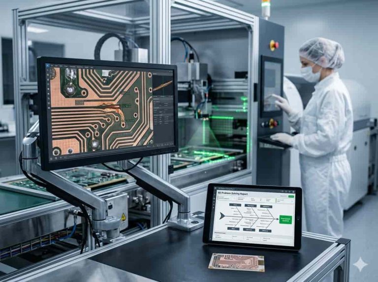
Why Manufacturing Precision Matters
In RF and 5G systems, the PCB itself becomes part of the transmission line.
Engineering precision must include:
-
Material traceability
-
Controlled lamination pressure
-
X-ray alignment verification
-
Impedance testing documentation
These capabilities are critical for OEM manufacturers scaling from prototype to mass production.
Frequently Asked Questions
1. What is a High Frequency PCB?
A High Frequency PCB is a circuit board designed with low-loss dielectric materials to support RF and microwave signals typically above 1 GHz.
2. Why is FR-4 not ideal for RF systems?
FR-4 has higher dielectric loss and inconsistent Dk values at high frequencies, leading to signal attenuation and instability.
3. What materials are commonly used in High Frequency PCBs?
Rogers, PTFE-based laminates, and low-loss hydrocarbon ceramic materials are widely used.
4. How important is impedance control in 5G PCB design?
Extremely important. Even small impedance deviations can cause signal reflection and degrade system performance.
5. Can High Frequency PCBs handle automotive temperature cycles?
Yes, when designed with appropriate materials and multilayer stack-ups, they can withstand -40°C to 125°C operating conditions.
The PCB Is the RF Backbone
Returning to the opening question:
“Why is the signal loss higher than expected?”
In RF and 5G systems, the answer often lies in the High Frequency PCB design and manufacturing precision.
From 5G base stations to automotive radar, satellite communication to microwave backhaul, high-frequency boards determine signal clarity, reliability, and system efficiency.
For OEM manufacturers, selecting the right fabrication partner ensures:
-
Predictable impedance control
-
Reduced signal attenuation
-
Scalable manufacturing consistency
-
Long-term performance stability
As frequencies climb and tolerances shrink, engineering discipline at the PCB level becomes the foundation of wireless innovation.
In RF systems, performance doesn’t start at the antenna.
It starts in the board.