The Paradigm Shift: Why Traditional Wire Harnesses Fail in High-Voltage EV Battery Packs
For over a decade, traditional wire harnesses served as the nervous system of battery packs, routing voltage and temperature sensing signals from individual cells to the Battery Management System (BMS). However, as automotive and Energy Storage Systems (ESS) push toward higher energy densities, increased automation, and tighter pack architectures, the mechanical and electrical limitations of discrete wiring have become a critical bottleneck.
Traditional wire harnesses introduce significant engineering vulnerabilities into modern high-voltage battery modules:
- High Manual Assembly Dependency: Routing dozens of individual wires, crimping terminals, and manually taping wire trees introduces a high rate of human error, leading to loose connections or miswiring during mass production.
- Volumetric Inefficiency: Discrete wiring bundles are inherently bulky. In modern cell-to-pack (CTP) or cell-to-chassis (CTC) designs, every millimeter matters. Wire trees consume critical space that could otherwise be utilized for active cell material or dedicated thermal management channels.
- Mechanical Fatigue Under Vibration: Automotive environments expose the battery pack to continuous, multi-axis harmonic vibrations. Crimp joints and point-contact terminals are prone to microscopic fretting corrosion and mechanical fatigue, risking localized resistance spikes or complete signal loss over time.
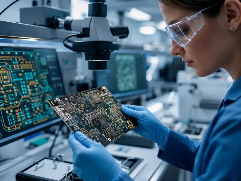
The Cell Contact System (CCS) solves these vulnerabilities by shifting from a 3D component-based assembly to an integrated 2D planar system. By embedding the intricate sensing circuits into a flexible printed circuit (FPC) and bonding it directly onto robust copper or aluminum busbars, the entire connection matrix is consolidated into a single, automated, drop-in module.
Materials & Stackup Physics: FPC Substrate Selection for Harsh EV Environments
Operating inside a high-voltage battery pack demands rigorous material characterization. Unlike consumer electronics where flexible circuits encounter mild conditions, a CCS FPC must survive continuous thermal cycling, exposure to potential electrolyte outgassing, and high dielectric stress.
The choice of core substrate material is a primary divider between commercial reliability and catastrophic field failure. While lower-cost alternatives like Polyethylene Terephthalate (PET) exist, premium automotive and medical-grade CCS architectures mandate the use of high-Tg Polyimide (PI).
⚡ Engineering Benchmark: Polyimide (PI) vs. Polyethylene Terephthalate (PET)
PET substrates degrade rapidly when subjected to temperatures exceeding 80°C and offer poor resistance to chemical solvents. Conversely, Polyimide maintains its structural, mechanical, and dielectric integrity across an extreme automotive operating window of -40°C to +105°C (and up to 150°C under transient overcurrent states). Furthermore, PI exhibits superior flame retardancy, easily meeting the mandatory UL 94 V-0 flammability standard required for thermal runaway mitigation.
To guarantee complete electrical isolation between the high-voltage busbars and the low-voltage BMS signal traces, the stackup configuration must be meticulously engineered. Standard CCS designs utilize a flexible coverlay—a layer of Polyimide film coated with a high-performance thermo-setting acrylic or epoxy adhesive. The adhesive thickness must be carefully calibrated to ensure complete encapsulation of the copper traces without creating “micro-voids” or adhesive starvation areas, which could trap moisture from condensation and initiate Conductive Anodic Filament (CAF) growth or localized dielectric breakdown.
Technical Benchmark: Traditional Wire Harness vs. Integrated FPC-CCS
The following technical data illustrates the quantifiable physical and electrical optimization achieved when transitioning to an integrated FPC-CCS module:
| Technical Parameters | Traditional Wire Harness Assembly | Integrated FPC-CCS Module (JS Circuit) |
|---|---|---|
| Assembly Labor & Automation | High manual routing, prone to human error | 100% automated Pick-and-Place & laser welding |
| Volumetric Space Consumption | Baseline (100%) – Bulky wire bundles | Reduced by 65% to 80% (Ultra-low profile < 1.5mm) |
| Total Module Weight | Baseline (100%) – Heavy copper/PVC | Reduced by 45% to 60% (Optimized mass) |
| Internal Resistance Consistency | Variable (±5mΩ based on crimp quality) | Ultra-precise (≤ ±0.2mΩ across all sensing lines) |
| Flame Retardancy Rating | Variable based on PVC/Teflon sleeving | Guaranteed UL 94 V-0 (Polyimide Core) |
| Component Integration | Limited to inline spliced sensors | Direct SMT integration of NTCs, Fuses & Connectors |
Metallurgical Mastery: Copper-to-Aluminum Dissimilar Welding Challenges
 in Next-Gen Battery Packs | JS Circuit INC")
Figure 1: Automated high-precision fiber laser welding production line. Real-time vision alignment tracks the contact interface between copper FPC pads and aluminum battery busbars before pulse detonation.
The most critical engineering hurdle in CCS manufacturing lies at the junction where the flexible circuit connects to the battery cell terminals: the metallurgical bonding of dissimilar metals. Direct fusion welding of copper (Cu) and aluminum (Al) is notorious for creating brittle Intermetallic Compounds (IMCs). These layers possess exceptionally high electrical resistance. Under mechanical stress, a thick IMC layer will micro-crack, leading to localized heating, sensor drift, or open-circuit failure.
To overcome this challenge, advanced manufacturing employs targeted energetic bonding technologies coupled with sophisticated surface finishes:
- Precision Laser Welding: Modulated fiber lasers allow for ultra-fast energy input, suppressing the growth of the brittle IMC layer to sub-micron thicknesses.
- Ultrasonic Wire/Ribbon Bonding: A solid-state welding alternative that entirely bypasses the liquid-to-solid IMC transformation phase.
- Nickel/Gold Barrier Plating: Depositing specialized nickel plating onto the copper contact pads acts as a physical buffer, eliminating galvanic corrosion risks.
Shock, Vibration, and Thermal Safety: Meeting Automotive Standards
To gain certification for electric vehicle deployment, a Cell Contact System must satisfy stringent automotive fatigue and environmental durability standards, such as ISO 16750 and the specialized IPC-6012DA (Automotive Requirements for Flexible Printed Boards).
During vehicle operation, structural shifting and thermal expansion of the battery cells exert continuous tensile and shear stresses. Professional DFM requires mechanical stress relief structures:
- O-Loops and S-Bends (Strain Relief): Curved loops in the FPC trace layout act as mechanical springs, absorbing the structural displacement during cycles.
- Polyester/Polyurethane Foam Lamination: Integrating structural foam dampens harmonic vibrations and protects critical laser-welded joints.
 in Next-Gen Battery Packs | JS Circuit INC")
Figure 2: Scanning Electron Microscopy (SEM) metallurgical cross-section. Analysis confirms that optimized multi-pulse laser sequencing curbs brittle Cu-Al intermetallic phase (IMC) growth to under 0.5 µm, passing rigid automotive shear-force requirements.
📋 Technical FAQ: Cell Contact System (CCS) Engineering
Q1: How does JS Circuit prevent galvanic corrosion at the copper-to-aluminum transition interface in CCS modules?
A1: We electroplate a dense Nickel barrier layer onto the copper sensing pads before laser welding to the aluminum busbars. This barrier blocks direct galvanic couple formation and moisture ingress, completely neutralizing the potential difference.
Q2: Why is IPC-6012DA compliance mandatory for EV-grade CCS FPC board fabrication?
A2: IPC-6012DA defines strict automotive criteria that exceed standard Class 3, regulating parameters like resin recession, micro-voiding, and thermal stress. Compliance ensures the FPC won’t suffer delamination under continuous 1,000-hour automotive THB testing.
Q3: Can NTC thermistors and surface-mount fuses be directly assembled onto the CCS FPC?
A3: Yes. SMT is standard. We design localized rigid FR-4 stiffeners directly underneath the component pads. This prevents solder joint cracking during subsequent flexible bending and installation into the battery tray.
Looking for customized, high-reliability Cell Contact System (CCS) architectures for your medical or automotive project?
Contact JS Circuit’s engineering team today for a comprehensive, complimentary DFM review.